Tuesday, January 14, 2020

Universal Arc Flash Analysis web app

ARCAD INC. has recently released new universal web app for arc flash hazard analysis and labeling. 

Capabilities:

  • The web app can be accessed, operated and shared from anywhere, anytime, on any platform connected to the Internet
  • Use it individually or share with your trusted team while working on same or multiple projects at a time
  • Forget about software installation, system compatibility, data loss or virus threat issues
  • Access to most recent services, updates and the most competitive price in the industry
  • Total transparency including but not limited to no subscription, no hidden fees nor contracts policy
  • Perform arc flash calculations using new IEEE 1584 year 2018 guide procedure
  • Save and edit equipment input configurations
  • Perform analysis using metric, imperial units
  • Calculate initial arc blast explosion pressure and arc flash explosive equivalent
  • Add fuse and circuit breaker data including time-current characteristics for the devices that are not already listed in the built-in protection device library
  • Chart fuse TCC and breaker trip characteristics
  • Save calculation results, equipment configuration, units of measurement in JSON, text format
  • Customize, save, print arc flash warning label
  • Perform arc flash boundary calculations based on 1.2 cal/cm2 (5 Joules/cm2) onset energy to second degree burn for bare skin exposure per IEEE 1584 Guide and other incident energy levels as well, such as the rating of proposed personal protective equipment, or evaluated onset to second degree burn energy

Billing strategy:

  • Sign-up free of charge and explore all functions listed above with the exception of system voltage input limited to 208 Volt in free demo or expired version of the app
  • Purchase year long access to the app with the possibility of purchasing more than one year access in advance
  • Check billing status, get notified when your account is close to expiration
  • Check billing history
  • If payment has not been made in a timely manner, the account status would automatically switch to expired and client would have to make payment to be granted access to the full version of the app (the 208V limit lifted)
Sign up free to arc flash analysis and labeling universal web app at app.arcadvisor.com

Thursday, December 6, 2018

Product Release - AFA V6.0


PRESS RELEASE
December 5, 2018
For Immediate Release
ARCAD INC.

Arc Flash Analytic version 6.0

The new software program for single- and three-phase arc flash hazard analysis & labeling is now available. 
TORONTO, ON - ARCAD INC. announces the release of AFA V6.0 software program for Windows operating systems.


New ARCAD's Arc Flash Analytic version 6.0 (AFA V6.0) software program conforming to the new IEEE 1584-2018 Guide for Arc-Flash Hazard Calculations has been released. The AFA V6.0 is a powerful, easy to use program for performing arc flash hazard analysis, creating detailed arc flash warning labels and obtaining compliance with OSHA, NFPA 70E 2018, CSA Z462 regulations and Electrical Code requirements.performs comprehensive study by taking into account system voltage, available fault current, equipment type, electrode configuration, working distance, gap between conductors and enclosure size. The new software program is applicable for:


  • Voltages in the range of 208 V to 15 000 V, three-phase (line-to-line).
  • Frequencies of 50 Hz or 60 Hz.
  • Bolted fault current (rms symmetrical):

    • 208 V - 600 V : 500 A to 106 000 A
    • 601 V - 15 000 V : 200 A to 65 000 A

  • Gaps between conductors:

    • 208 V - 600 V : 6.35 mm (0.25 in) to 76.2 mm (3 in.)
    • 601 V - 15 000 V : 19.05 mm (0.75 in) to 254 mm (10 in.)

  • Working distances of 305 mm (12 in) or larger
  • Fault clearing time: no limit
  • Enclosure dimension limits:

    • Maximum Height or Width: 1244.6 mm (49 in.)
    • Maximum Opening Area: 1.549 m2 (2401 in2)
    • Minimum Width: The width of the enclosure should be larger than four times the gap between conductors (electrodes).

  • Electrode Configurations:

    • VCB: Vertical conductors/electrodes inside a metal box/enclosure
    • VCBB: vertical conductors/electrodes terminated in an insulating barrier inside a metal box/enclosure
    • HCB: horizontal conductors/electrodes inside a metal box/enclosure
    • VOA: vertical conductors/electrodes in open air
    • HOA: horizontal conductors/electrodes in open air
    More information about AFA V6.0 software is available at http://arcadvisor.com/arc-flash-software


    ARCAD INC. located in Hamilton ON, Canada helps facilities create safer working environments for individuals who service electrical systems by providing on-line and stand-alone software resources for short circuit, arc flash hazard analysis and labeling. Visit us at http://arcadvisor.com

    More by ARCAD INC.


    Arc Flash Mobile

    # # #


    Friday, July 28, 2017

    ELECTRICAL SERVICES AND ARC FLASH TRAINING

    Electrical safety training, including arc flash training and shock hazard training, is not an option; it’s required by law, and recommended by industry standards. But it’s also the foundation of electrical safety, which protects your workers and your business. It’s an investment that will pay off.
    http://arcadvisor.com/faq/electrical-safety-arc-flash-training

    Wednesday, June 7, 2017

    The Elementary Safety Book for Children

    ARCAD is proud to sponsor The Elementary Safety Book for Children published by Maple Leaf Communications Inc. This free book is brought to children by businesses in local community. Do you know all the safety rules? An extensive team of animal experts show you how to play and stay safe both at home and when outside. Everything is more fun when you play safely!

    Sunday, June 4, 2017

    What's New? What's Changed? 2018 NFPA 70E Update

    The 2018 Edition of NFPA 70E is quickly approaching. Here is a link to an article by Jim Phillips / Brainfiller.com that was recently published in the May Edition of Electrical Contractor Magazine. As usual, some changes were minor, others were quite major. There is also quite a bit of reorganization.

    2018 NFPA 70E Changes Article

    PS: There are changes to the definition of arc flash boundary in the upcoming NFPA 70E Standard for Electrical Safety in the Workplace. Specifically, the revised definition of arc flash boundary no longer uses the term "second degree burn" but instead "at which incident energy equals 1.2 cal/cm2.", and the revised informational note references the Stoll skin burn injury model.

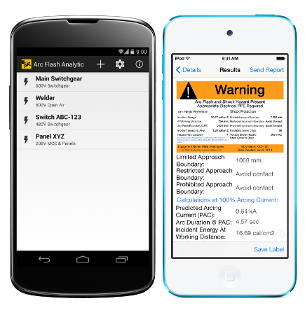
    NFPA 70E year 2004 assumed that the incident energy requirement increases below one second. A quote from NFPA 70E year 2004 "For situations where fault-clearing time is 0.1 second (or faster), the Flash Protection Boundary is the distance at which the incident energy level equals 6.24 J/cm^2 (1.5 cal/cm^2)." This reference was removed in NFPA 70E year 2012 edition. NFPA 70E year 2012 stated that "a second degree burn is possible by an exposure of unprotected skin to an electric arc flash above the incident energy level of 1.2 cal/cm2 ( 5.0 J/cm2 )" and assumed 1.2 cal/cm2 as a threshold incident energy level for a second degree burn for systems 50 Volts and greater. NFPA 70E year 2015 explicitly prohibited using incident energy and PPE category together. The NFPA Handbook from 2015 showed a sample label with fields to be filled in for "available incident energy" and "level of PPE" while just half a page earlier states that "available incident energy" cannot be included with the "PPE category" in table 130.7(c)15(A)(b).

    The revised definition of arc flash boundary in NFPA 70E year 2018 is even more misleading. It also contradicts the accompanying revised informational note referencing the Stoll skin burn injury model. A quote from A.Stoll "Heat Transfer in Biotechnology" summarizes the issue of using a critical thermal load approach in determining arc flash boundary. The quote reads:

    "Serious misconceptions have crept into this field of research through adoption of rule-of-thumb terminology which has lost its identity as such and become accepted as fact. A glaring example of this process is the “critical thermal load.” This quantity is defined as the total energy delivered in any given exposure required to produce some given endpoint such as a blister. Mathematically it is the product of the flux and exposure time for a shaped pulse. Implicit in this treatment is the assumption that thermal injury is a function of dosage as in ionizing radiation, so that the process obeys the "law of reciprocity," i.e., that equal injury is produced by equal doses. On the contrary, a very large amount of energy delivered over a greatly extended time produces no injury at all while the same "dose" delivered instantaneously may totally destroy the skin. Conversely, measurements of doses which produce the same damage over even a narrow range of intensities of radiation show that the "law of reciprocity" fails, for the doses are not equal."

    Here is what ASTM F1959/F1959M Standard Test Method for Determining the Arc Rating of Materials for Clothing says about skin burn injury determination:

    "12.1.4 Predicted Second-Degree Skin Burn Injury Determination (Stoll Curve Comparison) — The time dependent averaged heat energy response for each panel [..] is compared to the Stoll Curve empirical human predicted second-degree skin burn injury model:

    Stoll Response, cal/cm2 = 1.1991 * ti^0.2901

    where ti is the time value in seconds of the heat energy determination and elapsed time since the initiation of the arc exposure. A second-degree skin burn injury is predicted if either panel sensor heat energy response exceeds the Stoll Response value (at time ti)."

    Incident energy alone has no impact on thermal damage and blast pressure. One can expose himself to any arbitrary incident energy and suffer no damage as long as the energy is delivered at slow enough rate. On the other hand, an exposure to only a fraction of 1.2 cal/cm2 may result in incurable burn provided that the energy has been delivered fast enough. Read Evaluation of onset to second degree burn energy in arc flash hazard analysis for more information. The issue of using incident energy as a measure of damage alone and without regard to the rate of the energy release has been raised to NFPA 70E committee before year 2015 edition was published but unfortunately it was never appropriately addressed by the group.

    Sunday, December 18, 2016

    Recommended Guidelines for Arc Flash Labeling

    Whenever an arc-flash study is done or revised and new arc flash warning labels must be considered, it is a good idea to define exactly what information belongs on each label before starting to print anything. It is also a good idea to define how and where these labels will be applied before anyone peels the back off of the first adhesive label and sticks it onto anything. It is a very good idea to put those definitions into writing so that everyone who assists or who comes along later, has something to help them understand the original intent. This is particularly important as a means of trying to promote consistency and to avoid creating unnecessary confusion when an arc flash analysis study is spread out over extended period of time. A guideline document such as the one published here serves that purpose. The guideline describes how electrical equipment should be labeled, namely how many labels should be applied and in which locations, after appropriate data collection, modeling, short-circuit analysis and arc-flash study activities have been completed. The intent here is not to limit the number of labels applied but rather to insure that at least the required minimum number of labels are in place. This document also addressed the question of how to label devices that were subject to protection under a selectable maintenance settings scheme. This application involved two labels as shown in Figure 6.

    The arc-flash labels discussed herein are required by the NEC in article 110.16 and by NFPA 70E in Section 130.7 (E)(1). There are two basic types of arc flash labels that should be used. They are a generic label - one that does not include specific calculated data but which identifies the existence of the hazard and refers the reader to the site 70E policy, and a specific label - one that includes calculated data for arc-flash incident energy or hazard/risk category and identifies specific required PPE. Figure 1 shows one of each type of label, with the generic type being the upper label. This guideline identifies what type of equipment we should be labeling and how to label that equipment. If a piece of equipment is identified by company guidelines as within the scope of equipment for which we should be calculating arc-flash exposure, then the label should be a specific label. Otherwise, the label will be a generic label and will refer to the overall site 70E policy. Wherever specific labels are applied, they shall describe all of the requisite PPE.

    generic arc flash label
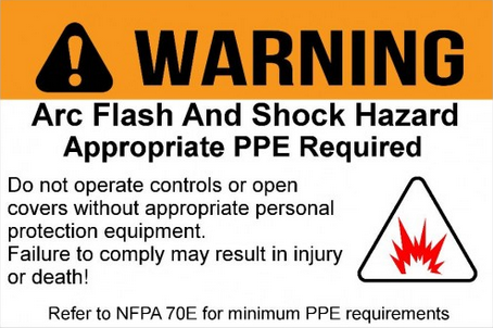
    Figure 1A. An example of generic arc flash warning label.

    arc flash warning label sample
    Figure 1B. An example of specific arc flash warning label.

    Many facilities have been through short-circuit and arc-flash studies conducted under previous versions of the NFPA 70E regulation. In such cases, it is possible that the labels already in place in the field reflect older hazard levels and types of PPE for some of the labeled equipment and are no longer correct for the current version of NFPA 70E. It is permissible to hand-modify the existing labels if the changes are somewhat minor, but it is often confusing to do that. The preferred approach is to relabel the equipment. However, since the current version of the regulation requires review and update on a five-year cycle, it is recommended that the labels simply be corrected during the course of the next overall update.

    The generic label is a Brady product, while the specific label is a product printed as output from Arc Flash Analytic software program. Both of these labels use the ANSI Z535.4 "warning" format and an orange banner. The "danger" format with a red banner, described in the same ANSI standard, is equally acceptable.

    Read more at http://arcadvisor.com/faq/arc-flash-labeling-guidelines

    Wednesday, December 7, 2016

    Guide To Arc Flash Apps. Simple solutions for fast and accurate results.

    Arc flash applications are increasing in popularity among engineers and electricians when examining hazards presented by an arc flash. Professionals search for accessible tools to help reduce dangers associated with arc flash as well as to assist in selecting adequate personal protective equipment (PPE). Mobile apps for arc flash analysis can be useful for assessing the hazards before working on energized equipment. 

    Contrary to many simple and complex computer programs used for power system and arc flash hazard analysis, only a handful of arc flash apps are available for purchase. Each app, available in either the Apple Store (iPhone) or Google Play (Android-operated devices), vary in level of complexity and range of operations. 

    Q: What are some specific benefits to workers using arc flash apps on their mobile device?

    Qualified workers use mobile apps for data collection, field analysis of electrical equipment and evaluation of arc flash dangers when access to complex power system analysis computer software is limited or not available. Electrical and safety professionals can now find ways to minimize arc flash hazards using handheld gadgets while in the field by trying different protection device settings and by simulating various fault scenarios. 

    The apps help in meeting the requirements of CSA Z462 "Workplace Electrical Safety" and NFPA 70E: "Standard for Electrical Safety in the Workplace" published respectively by the Canadian Standards Association and the National Fire Protection Association. Arc flash mobile apps support calculations and functions for typical distribution systems that use fuses and circuit breaker protection devices. They provide for real-time display of incident energy and arc flash boundary results